2.1.3. Element* Components
2.1.3.1 Analyse
- Mesh Closest Point
- Mesh Evaluate
- Mesh Sample Plus
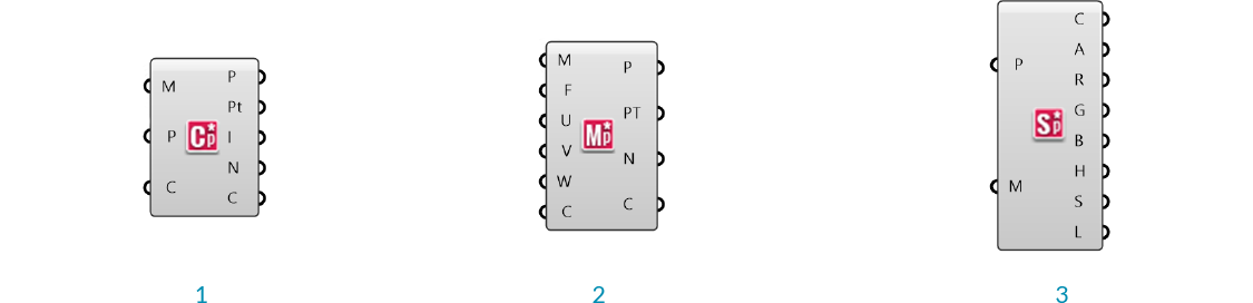
Element* Mesh Closest Point
Unlike Grasshopper's Mesh Closest Point component, this component also calculates the normal and color at the outputed point, eliminating the need for a Mesh Eval component and simplfying the canvas workspace.
Element* Mesh Evaluate
The built in Grasshopper Mesh Eval component requires a mesh parameter as an input, which can be extracted from a Mesh Closest Point component, but which can be difficult to construct manually. Element's closest point component allows direct input of the index of a mesh face and the barycentric coordinates.
Note - barycentric coordinates are defined such that they always add to 1. If the input values of U,V, and W do not add to 1, this component will maintain the ratio of the three values while normalizing them. For example, if you had the input values of 2, 2, and 4 the mesh parameter would be calculated as {0.25;0.25;0.5}
Element* Mesh Sample Plus
This component is used to quickly extract color information from a mesh. It returns the Alpha, Red, Green, Blue, Hue, Saturation, and Luminosity values of the inputed points. If the given points are not on the mesh, this component will calculate the closest point. This component uses Parallel Computing for speed.
2.1.3.2 Data
- Data Visualizer
- Edge Neighbors
- Face Neighbors
- Vertex Neighbors
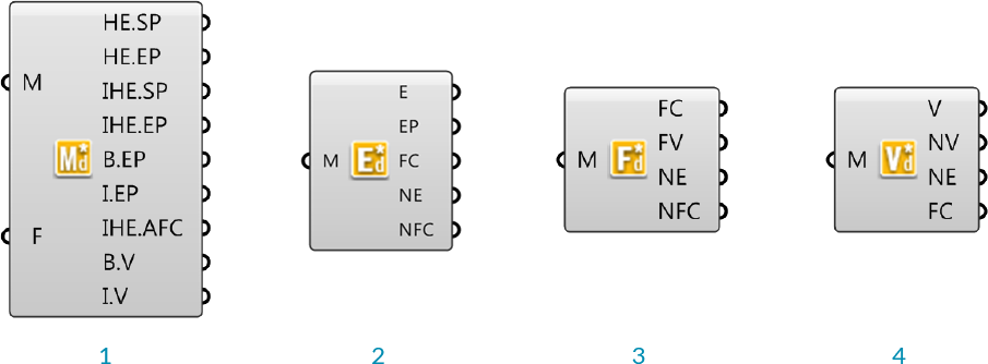
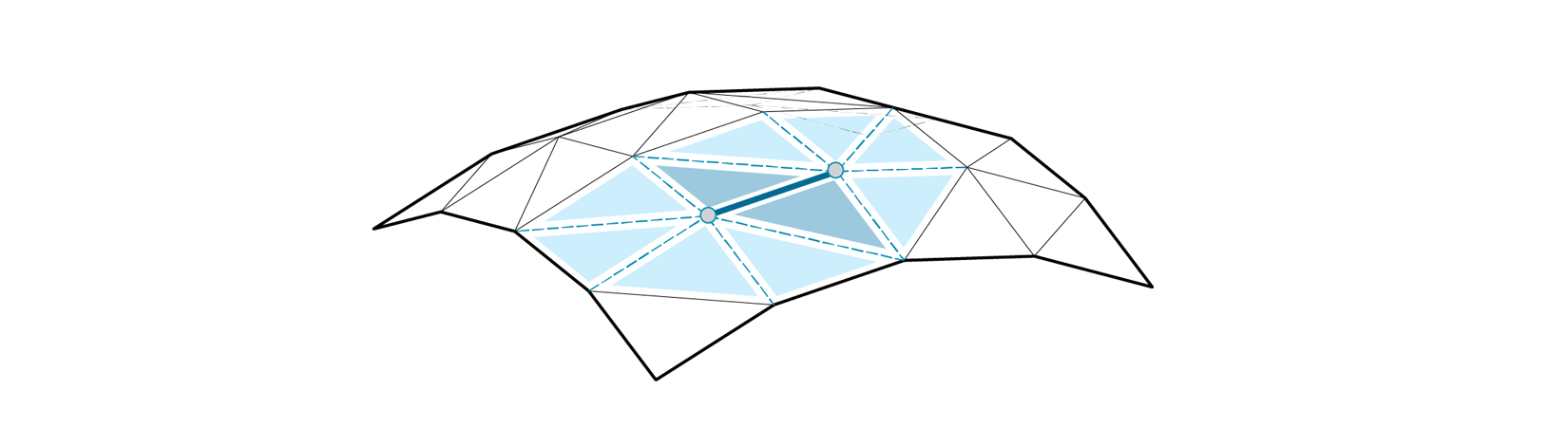
Element* Data Visualizer
This component is used to help visualize the half-edge data of the faces of an input mesh.
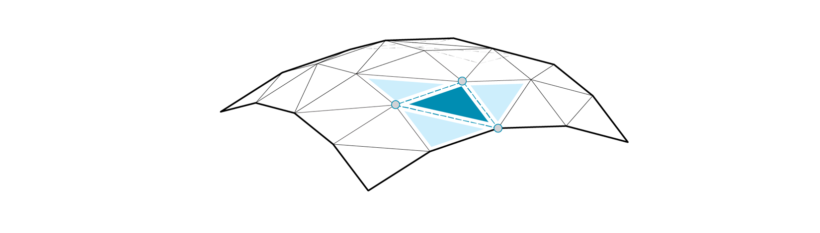
Element* Edge Neighbors
This component provides access to the adjacency data structured according to the edges of the input mesh. The output data is provided as a tree with one branch for each edge in the mesh. It returns the mesh edges, the edge end points, center ponts of the faces adjacent to each edge (dual), the neighboring edges as line objects (arranged in clockwise order) , and neighbouring face centers (center points of faces adjacent to the edge start and end points)
Edge Neighbors - Edges, End vertices, Adjacent face centers, Neighboring edges, and Neighbouring face centers
Element* Face Neighbors
This component is similar to the others in this section, but the data is organized in a tree according to the faces of the mesh, with one branch per face. The outputs are the face centers, vertices of each face (arranged in counter clockwise order), neighbouring edges (arranged in counter clockwise order), and the centers of neighboring faces (arranged in counter clockwise order).
Face Neighbors - Face centers, face vertices, neighbouring edges, neighbouring face centers
Element* Vertex Neighbors
This component outputs the mesh vertices, neighboring vertices (arranged in clockwise order), neighbouring edges (arranged in clockwise order), and neighbouring face centers (arranged in clockwise order) structured in a tree according to the vertices of the mesh.
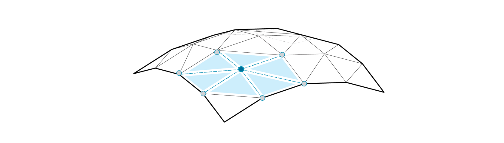
Vertex Neighbors - Vertices, neighbouring vertices, neighbouring edges, neighbouring face centers
2.1.3.3 Primitives
Element* provides four additional mesh primitives: the Dodecahedron, Tetrahedron, Octahedron, and Icosahedron. These components take a single number as input for the radius, and produce meshes centered at the origin, and composed of one face per side. With the addition of the Cube, which is already availible through Grasshopper's built-in primitives, these make up the five Platonic solids.
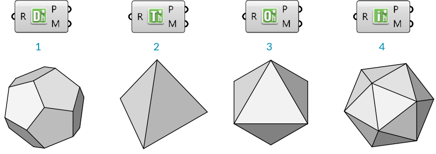
- Dodecahedron
- Tetrahedron
- Octahedron
- Icosahedron
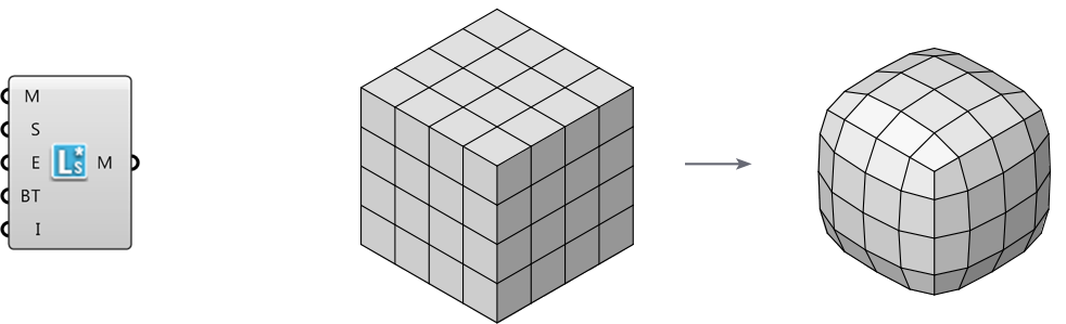
2.1.3.4 Smooth
Element* Smooth provides an optimized smoothing algorithm that is more efficient than Grasshopper's Smooth Mesh for large datasets. It makes use of the Lapacian Smoothing algorithm for Half-Edge structured meshes. It does not change the topology or vertex count of welded meshes, but will combine identical vertices if there are any duplicates caused by an unwelded mesh. We can specify the smoothing strength, boundary condition, boundary tolerance as well as the number of iterations.
2.1.3.5 Subdivide
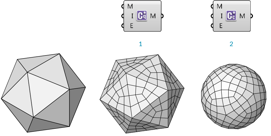
Element* Catmull Clark Subdivision
This is a recursive subdivision defined by the Catmull Clark algorithm. We can specify the number of iterations as well as how to handle naked edge conditions.
Element* Constant Quad
This subdivison component will create an all quad mesh by adding a face for each edge of the mesh.
- Constant Quad subdivision
- Catmull Clark subdivision
2.1.3.6 Transform
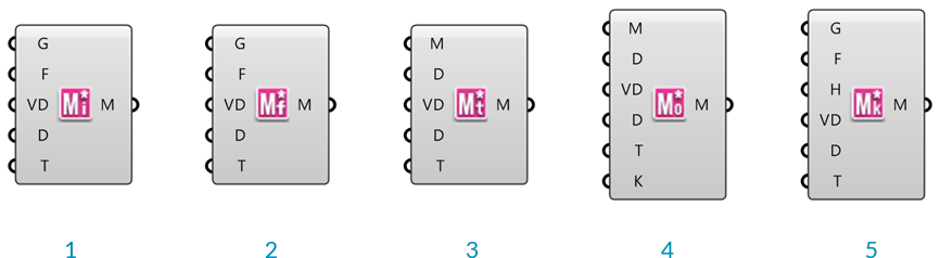
- Mesh Windown
- Mesh Frame
- Mesh Thicken
- Mesh Offset
- Mesh Poke Face
These components provide a number of different transformations described below. Each component has the additional capability of accepting per-vertex distance data to allow for variations of the transformation magnitudes across the mesh.
Element* Mesh Window
Reconstructs a new mesh on the inside of a face based on an offset value. This component accepts either a mesh or a list of closed polylines as input.
Element* Mesh Frame
Outputs a frame around mesh faces. Each resultant face will have a new hole in the center. This component accepts either a mesh or a list of closed polylines as input.
Element* Mesh Thicken
This component will thicken an input mesh along the vertex normals, and according to provided distance values.
Element* Mesh Offset
This component creats an offset of the input mesh based on the vertex normals.
Element* Mesh Poke Face
First the mesh face goes through the frame operation then the face inner is split the selected faces and allows the user to specify the push or pull amount from the center of the original polygon. For example, a four-sided polygon (quad) is split into 4 three-sided polygons with one shared vertex in the middle. The height input allows you to transform that vertex.
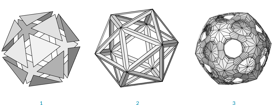
- Mesh Window
- Mesh Frame
- Icosohedron transformed with mesh frame, then thickend and subdivided
2.1.3.7 Utility
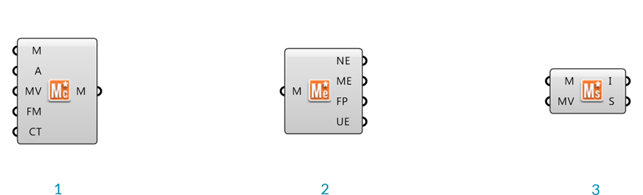
- Mesh Combine & Clean
- Mesh Edges
- Mesh Status
The Element* Mesh Combine and Clean
This component combines multiple meshes, has options for either welding a mesh based on input angle or combining identical vertices. We can also flip the orientation of the mesh. This component also detects potential topology issues and returns Remarks and Warnings with detailed explanantions. In the event that combining identical vertices creates bad topology the component will return the input list of meshes instead of a combined merged mesh. The user can also choose to combine the mesh without merging any of its vertices.
The Element* Mesh Edges
This component returns the mesh naked edges, mesh edges, face polylines and if the mesh is unwelded it will return the unwelded mesh edges.
The Element* Mesh Status
This component returns mesh information based on the topology. There are two modes which we can view the information, the first is Mesh Info which returns Geometry data such as Mesh Validity, Vertex Count, Face Count, and Normal Count. The other returns the Mesh Status, which is the condition of the mesh, whether it has non manifold edges, degenerate face count, naked edge count, and disjoined mesh count. This component does not operate on a mesh it simply returns the information to the user. There is also an option to combine identical vertices, therefore the user can see the effects this would have on the mesh.