2.1.4. Exercise
In this section, we will work through a simple exercise using the Element* primitives as a base. We will incorporate the half-edge data structure as well using both features of the transform components (uniform and per vertex)
Example files that accompany this section: Download
| 01. | Start a new definition, type Ctrl-N (in Grasshopper) | |
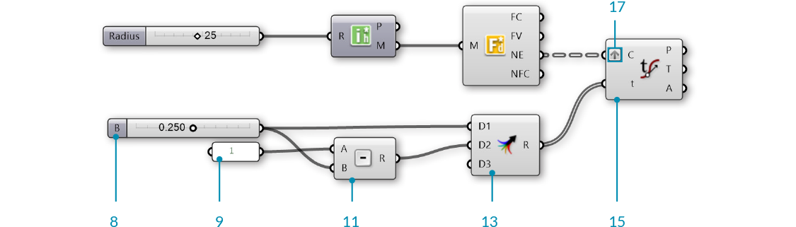
| 02. | Element*/Primitive/Icosohedron - Drag and drop the Icosohedron component onto the canvas |  |
| 03. | Params/Input/Number Slider - Drag and drop the Number Slider component onto the canvas | |
| 04. | Connect the Number Slider to the Radius (R) input of the Icosohedron component | |
| 05. | Double-click the Number Slider and set appropriate values. For this example, we used:
Rounding: Integer Lower Limit: 5 Upper Limit: 50 Value: 25 |
|
| 06. | Element*/Data/Face Neighbors - Drag and drop the Face Neighbors component onto the canvas |  |
| 07. | Connect the Mesh (M) output of the Icosohedron component to the Mesh (M) input of the Face Neighbors component. |

Looking at the data of the Neighboring Face Edges (NE) output, we see that we have a tree with 20 branches, where each branch contains three lines. The 20 branches each represent a face of the icosohedron which has 20 sides, while the three lines are the edges of each triangular face.
| 08. | Params/Input/Number Slider - Drag and drop a Number Slider component onto the canvas and set the following values:
Lower Limit:0 Upper Limit: 0.5 |
|
| 09. | Params/Input/Panel - Drag and drop a Panel component onto the canvas | |
| 10. | Double-click the Panel component and enter "1" into the text-field | |
| 11. | Math/Operators/Subtraction - Drag and drop a Subtraction component onto the canvas |  |
| 12. | Connect the Panel with a value of "1" into the A input and connect the number slider to the B input of the Subtraction component | |
| 13. | Sets/Tree/Merge - Drag and drop a Merge component onto the canvas |  |
| 14. | Connect the Number Slider to the D1 input of Merge, and connect the output R of the Subtraction component to the D2 input of Merge | |
| 15. | Curve/Analysis/Evaluate Curve - Drag and drop an Evaluate Curve component onto the canvas |  |
| 16. | Connect the Face Edges (NE) output of the Face Neighbors component to the Curve (C) input of the the Evaluate Curve component | |
| 17. | Right click the Curve (C) input of the Evaluate Curve component and select Graft. This will create a new branch for each edge. | |
| 18. | Connect the Result (R) output of the Merge component to the Parameter (t) input of the Evaluate Curve component. Because we grafted the Curve input, each edge is evaluated at both parameters from Merge |
| 19. | Sets/Tree/Trim Tree - Drag and drop a Trim Tree component onto the canvas |  |
| 20. | Connect the Points (P) output of Evaluate Curve to the Tree (T) input of the Trim Tree component. The default value of Depth (D) input for **Trim Tree** is 1. This reduce the depth of our data tree one level by merging the outer most branch. The result is 20 branches, each with six points. |
|
| 21. | Curve/Spline/Polyline - Drag and drop a Polyline component onto the canvas |  |
| 22. | Connect the Tree (T) output of the Trim Tree component to the Vertices (V) input of the Polyline component | |
| 23. | Right click the Closed (C) input of the Polyline component, click "Set Boolean" and set the value to True This has created a closed polyline of six sides for each original face of the mesh. |
|
| 24. | Element*/Transform/Mesh Frame - Drag and drop a Mesh Frame component onto the canvas. |  |
| 25. | Connect the Polyline (Pl) output of the Polyline component to the Geometry (G) input of the Mesh Frame component Note that the **Mesh Frame** component can take either meshes or a list of closed polyline curves as input |
|
| 26. | Params/Input/Number Slider - Drage and drop a Number Silder component onto the canvas. We will keep the default range of 0 to 1 for this slider | |
| 27. | Connect the Number Slider to the Factor (F) input of the Mesh Frame component |
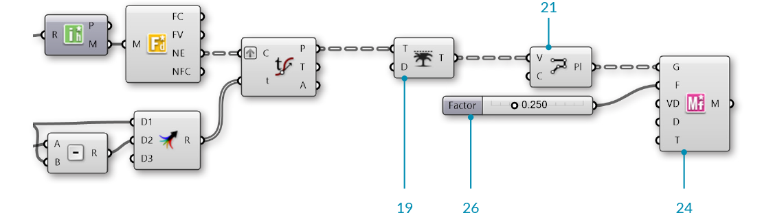
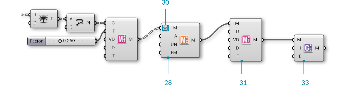
| 28. | Element*/Utility/Mesh Combine and Clean - Drag and drop a Mesh Combine and Clean component on the canvas | 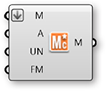 |
| 29. | Connect the Mesh (M) output of Mesh Frames to the Mesh (M) input of the Mesh Combine and Clean component | |
| 30. | Right click the Mesh (M) input of Mesh Combine and Clean and select Flatten By flattening the tree of meshes, **Combine and Clean** will merge all 20 face meshes into a single mesh |
|
| 31. | Element*/Transform/Mesh Thicken - Drag and drop a Mesh Thicken component onto the canvas |  |
| 32. | Connect the Mesh (M) output of Combine and Clean to the Mesh (M) input of Mesh Thicken | |
| 33. | Element*/Subdivide/Catmull Clark Subdivision - Drag and drop a Catmull Clark Subdivision component onto the canvas |  |
| 34. | Connect the Mesh (M) output of Mesh Thicken to the Mesh (M) input of the Catmull Clark Subdivision component |
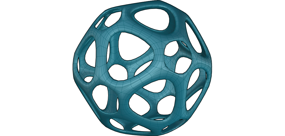
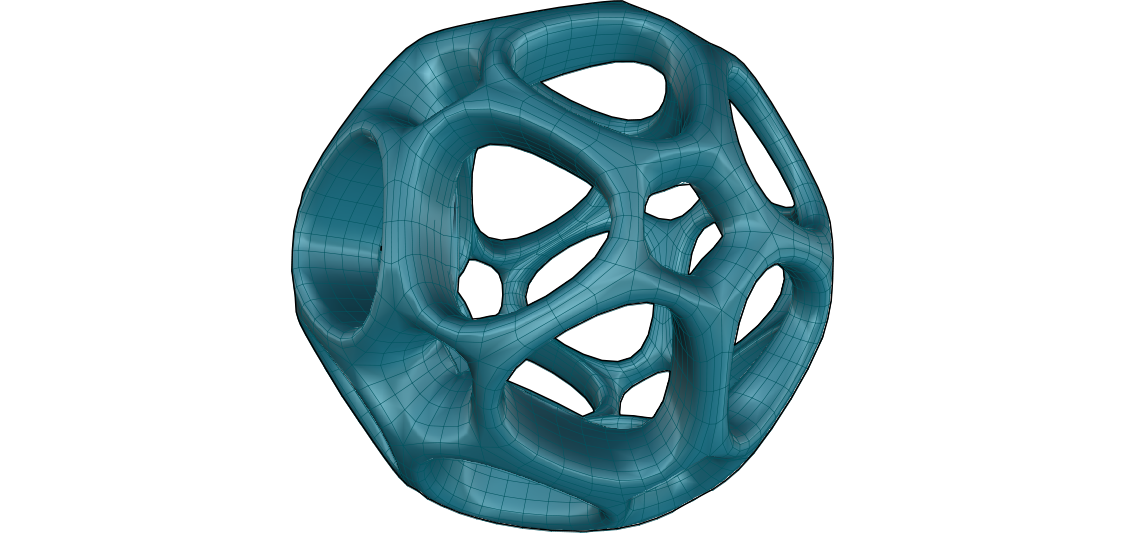
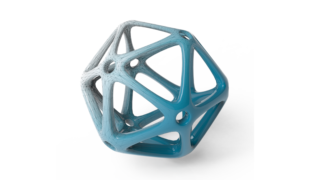
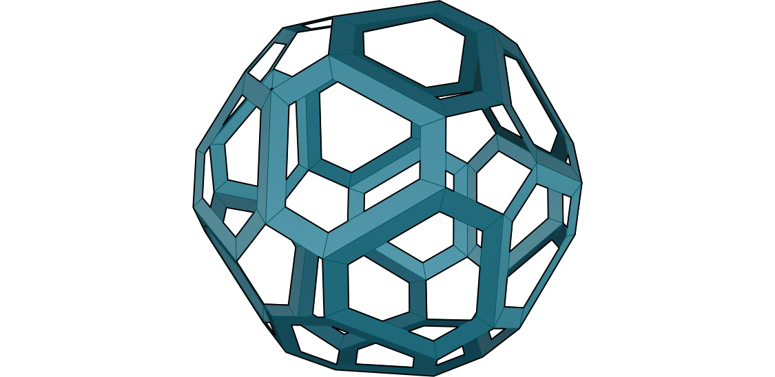
We have truncated the triangular faces of the initial mesh, effectively also creating rings around each original vertex. We have also created a frame for each face, then thickened the mesh and refined it with subdivision. Next we will take advantage of the Per Vertex capabilities of the transform components by using an attractor point.
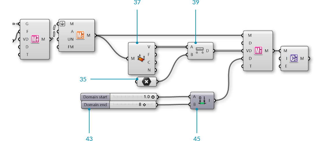
| 35. | Params/Geometry/Point - Drag and drop a Point parameter onto the canvas |  |
| 36. | Right click the Point parameter and select "Set on point" to select a point in the Rhino viewport Tip - you can also create a point directly in Grasshopper by double-clicking the canvas to bring up the Search window, then typing a point coordinate such as "10,10,0" (without the quotes) |
|
| 37. | Mesh/Analysis/Deconstruct Mesh - Drag and drop a Deconstruct Mesh component onto the canvas |  |
| 38. | Connect the Mesh (M) output of the Combine and Clean component to the Mesh (M) input of the Deconstruct Mesh component. We will use this to extract the vertices of our combined mesh, and then apply an attractor point to these vertices |
|
| 39. | Vector/Point/Distance - Drag and drop a Distance component onto the canvas |  |
| 40. | Connect the Vertices (V) output of the Deconstruct Mesh component to the A input of the the Distance component | |
| 41. | Connect the Point parameter to the B input of the Distance component | |
| 42. | Connect the Distance (D) output of the Distance component to the PerVectex Data (VD) input of the Thicken component | |
| 43. | Params/Input/Number Slider - Drag and drop two Number Slider components onto the canvas. We will use these to set the lower and upper limits for the Mesh Thicken component | |
| 44. | Double-click the Number Sliders and set the values. In this example, we left the first slider at default values, and set the Upper Limit of the second slider to 5.0 | |
| 45. | Maths/Domain/Construct Domain - Drag and drop a Construct Domain component onto the canvas |  |
| 46. | Connect the two number sliders to the A and B inputs of the Construct Domain component | |
| 47. | Connect the Domain (I) output of the Construct Domain component to the Min and Max Values (D) input of the Mesh Thicken component. | |
| 48. | Right click the Type (T) input of the Thicken component, select "Set Integer" and enter a value of 1 You can also enable the PerVertex Data by using a **Boolean Toggle** component set to True. |